Go Back   XmodSource.com > Xmods > XMOD Electronics
Register FAQ Members List Calendar Gallery iTrader Today's Posts

Reply
 
Thread Tools Display Modes
  #1  
Old 05-09-2011, 07:07 PM
xxmoderxx xxmoderxx is offline
Advance member
 
Join Date: Dec 2008
Posts: 101
Trader Rating: (0)
Default i kould use a little help

does anyone know how to wire a micro-t pcb to an xmods?? also is there a wiring diagram for the micro-t esc?
Reply With Quote
  #2  
Old 05-09-2011, 10:06 PM
XMDrifter's Avatar
XMDrifter XMDrifter is offline
drifter and engineer
 
Join Date: Jul 2006
Location: St Louis
Posts: 2,179
Trader Rating: (5)
Send a message via AIM to XMDrifter
Default

there might be one floating around in the forums. try the search function for "micro-t board swap"

i vaguely remember there being one, but don't remember which section of the forum its in.
__________________
Reply With Quote
  #3  
Old 05-09-2011, 10:35 PM
xxmoderxx xxmoderxx is offline
Advance member
 
Join Date: Dec 2008
Posts: 101
Trader Rating: (0)
Default

ckouldnt find one
Reply With Quote
  #4  
Old 05-09-2011, 11:26 PM
stangcannon stangcannon is offline
New Member
 
Join Date: May 2010
Posts: 17
Trader Rating: (0)
Default

2.8 did this for my bros car

Quote:
Originally Posted by 2.8-350TBI View Post
I didnt have to work tonight, but I drank a monster thinking I was gonna work, so I came back home and was still wired... So... I decided to start work on this beast.

The first thing I did was take apart the motor, and inside I found a set of old school (china toy) wiper brushes. So I did away with those. After, I wound a custom arm, but I messed it up, so I grabbed a gen 1 stage 2, and took the endbell, brushes, and armature and slapped em onto the motor the car had.

Next was to remove all the wiring and clean up messy solder. Check.

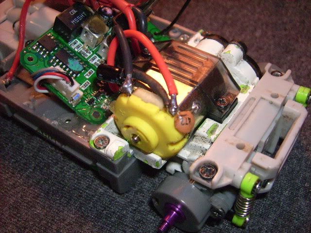
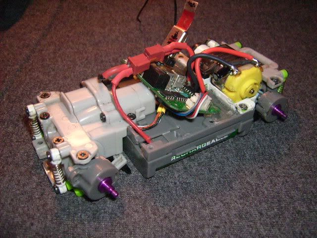
Next chore was to wire up the board to the xmod pot and steering motor. It wasnt too bad. I got it on my first try
The pot wires are like this

Micro-T---------XMODS
POT
Black-Black
Red-Orange
White-White

Steering:
Blue-White
Gray-White/black stripe.

Soon after testing I trimmed the wires to length, soldered and heatshrinked them, and hot-glued the board to the car, and finally tucked all the wires under the board.

http://www.youtube.com/watch?v=7GiOiWSgkcc

Looks pretty, and the electronics are pretty nice and have a smooth and linear response!


Reply With Quote
  #5  
Old 05-09-2011, 11:47 PM
xxmoderxx xxmoderxx is offline
Advance member
 
Join Date: Dec 2008
Posts: 101
Trader Rating: (0)
Default

i know the steering and stuff i need to know where the power, motor, etc wires go.
Reply With Quote
  #6  
Old 05-10-2011, 06:56 AM
stangcannon stangcannon is offline
New Member
 
Join Date: May 2010
Posts: 17
Trader Rating: (0)
Default

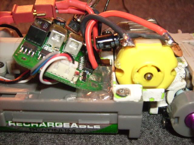
Well if you have the board in front of you the farthest fet is negative then the one next to it is positive these are for the motor and the solder point next to that fet is the positive terminal for the battery and right next to that is the negative one does this help any?
Reply With Quote
  #7  
Old 05-10-2011, 08:15 AM
xxmoderxx xxmoderxx is offline
Advance member
 
Join Date: Dec 2008
Posts: 101
Trader Rating: (0)
Default

yes actually. thanls and do i have to solder anything else to the board??
Reply With Quote
  #8  
Old 05-10-2011, 10:06 AM
stangcannon stangcannon is offline
New Member
 
Join Date: May 2010
Posts: 17
Trader Rating: (0)
Default

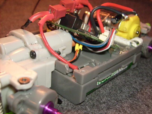
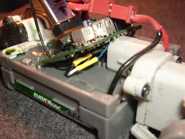
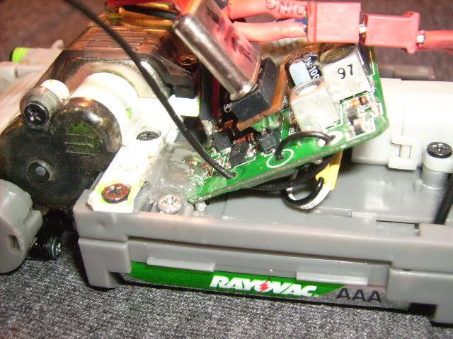
Nope the servo is just a plug that goes in and if the motor spins backwards just switch the motor wires if you look at the pics of my bros car you can see the wires were switched because this board didn't run the same way as his other one
Reply With Quote
  #9  
Old 05-10-2011, 06:49 PM
xxmoderxx xxmoderxx is offline
Advance member
 
Join Date: Dec 2008
Posts: 101
Trader Rating: (0)
Default

what about the power switch or something. i see solder contacts on the bottom.
Reply With Quote
  #10  
Old 05-10-2011, 10:30 PM
stangcannon stangcannon is offline
New Member
 
Join Date: May 2010
Posts: 17
Trader Rating: (0)
Default

All soldering for the motor and batterys are on the side of the board with the crystals and you can get rid of the power switch just solder a jumper wire from the positive to negative solder points on the board for the switch it basicly just gives it a complete circuit so it doesnt have to be controled
Reply With Quote
  #11  
Old 05-10-2011, 10:54 PM
xxmoderxx xxmoderxx is offline
Advance member
 
Join Date: Dec 2008
Posts: 101
Trader Rating: (0)
Default

okay ckool kan i use a mini-z remote and xmods crystals with this ESC??
Reply With Quote
  #12  
Old 05-10-2011, 11:26 PM
stangcannon stangcannon is offline
New Member
 
Join Date: May 2010
Posts: 17
Trader Rating: (0)
Default

The crystals are a yes but the remote im not sure on you may have to buy a losi one
Reply With Quote
  #13  
Old 05-10-2011, 11:29 PM
xxmoderxx xxmoderxx is offline
Advance member
 
Join Date: Dec 2008
Posts: 101
Trader Rating: (0)
Default

oo okay thankss alot

also for future reference it does work with mini-z remote and xmods crystals.

Last edited by DRFTKO; 05-11-2011 at 05:00 PM.. Reason: double post
Reply With Quote
Reply


Currently Active Users Viewing This Thread: 1 (0 members and 1 guests)
 

Posting Rules
You may not post new threads
You may not post replies
You may not post attachments
You may not edit your posts

BB code is On
Smilies are On
[IMG] code is On
HTML code is Off

Forum Jump


All times are GMT -4. The time now is 12:58 AM.


Powered by vBulletin® Version 3.8.7
Copyright ©2000 - 2024, vBulletin Solutions, Inc.