
|
|
#1
|
||||
|
||||
|
A Mosfet is a Metal Oxide Semiconducting Field Effect Transistor.
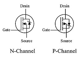
Generally they come in 2 types. n-channel and p-channel. These essentially are high speed switches that can be turned on and off at speeds that are impercievable by humans. Let's go through them. N-Channel FET: 3 leads coming from the transistor: -source lead connected to ground, or negative, -drain lead is connected to the load's negative tab. (or whatever is upstream) -gate lead's signal controls the on/off state of the transistor, a low signal meaning off, and a high signal meaning on. P-Channel FET: Like the N-channel, 3 leads coming from the transistor, however different connections and behavior: -source lead connected to positive -drain lead is connected to the load's positive tab (or whatever is downstream) -gate lead's signal controls the on/off state of the transistor, a low signal meaning on, and a high signal meaning off.  How does this relate to/or is useful for xmods? Well, for starters, xmod FET's run on what's called an H-bridge. This is a combination of 2 N-channel mosfets and 2 P-channel mosfets to make a reversible motor control. Here is a circuit diagram:  How this works is that when both the left pair of transistors (the n and P channel fets) and the right pair of transistors are given a low signal, the circuit is off with both n-channel transistors off, and p channel transistors on (does nothing since there is no voltage potential difference). When the left side's gate signal goes to high, it turns off the left side p-channel and connects the n-channel on the left. since the right side's unchanged, the current passes through the conencted p-channel on the right side, through the load in the middle, and then down through the n-channel to ground. When the left and right side signals are reversed, the current travels through the load in the opposite direction. this means it runs in reverse, if it's a brushed dc motor. Wait wait wait, xmods only have 2 fet's and both have 8 legs! alright. good you noticed. Xmods Gen1 run on an IC (Integrated circuit) that embeds 2 transistors into 1 chip. (1 n-channel and 1 p-channel). These share the motor output leads, however the input leads are still separate for gate signals to control each of the two transistors in the chip. This means the outputs can all be melded together for each chip. P-N dual combination chip datasheet: http://www.vishay.com/docs/70717/70717.pdf Xmods Evo use two IC's. one is a dual n-channel, and the other is a dual p-channel. this means one of the IC's contains two n-channel transistors, and the other contains two p-channel transistors. dual P-channel datasheet: http://www.irf.com/product-info/data...ta/irf7324.pdf dual N-channel datasheet: http://www.irf.com/product-info/data...ta/irf9910.pdf Going according to the h-bridge circuit diagram, this means that you cannot glob all four pins on the output side together in this case, but rather you have to solder them together in pairs instead. Duty cycle: this is where variable speed control comes from. when duty cycle = 100%, there's no oscillating between high and low signals for either the left or right side of the h-bridge. this means that maximum current passes through. at 50% duty cycle, half of the time, the signal is high, and the other half of the time, it's low (cycling between high and low evenly) at 0% duty cycle, the circuit is completely turned off. This is a fairly easy to grasp concept. It literally is how much percentage of the signal's time is spent on a high signal. How does this vary speed? it switches so quickly on and off, that the motor sees an analog-like varied current input. It then acts like it runs at whatever percent of max voltage that the duty cycle is at. So with this knowledge, can we make FET boards ourselves? yes. yes you can. look up the mosfets that are on your xmod, and find their pinout diagram. with that, you can know where the gate signal is coming from, so you can design your fet board around it. (the PDF's posted above have these pinout diagrams available, as well as aid in figuring out the chip orientation on the board.) what you want is a very very fast response time to respond to all the digital steps, while maintaining a high current passing capacity. of course, this also brings you one step closer to making your own darn xmod pcb if you wanna go crazy and learn FM radio circuitry and programmable logic chips. Cheers and happy new years!
__________________

|
|
#3
|
||||
|
||||
|
figured when i returned to XMS i'd do something productive.
also, i'm sad that XMS activity is like a ghost town. we were so enthusiastic about it when xmods were still out...
__________________

|
 |
| Currently Active Users Viewing This Thread: 1 (0 members and 1 guests) | |
|
|