
|
|
#1
|
||||
|
||||
|
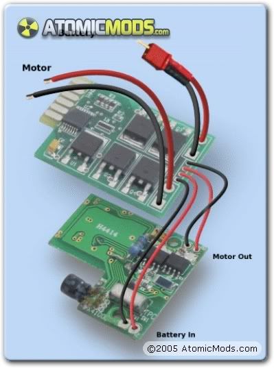
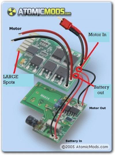
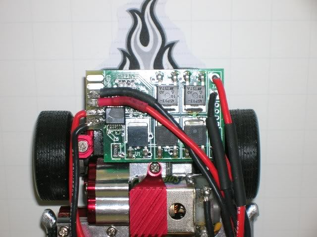
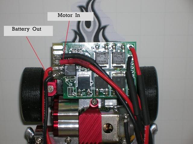
I actually got this from Atomicmods.com I talked to Christian and he told me this secret. (I don't know if it's a secret, but if you didn't know then here we go) on the V2.2 where you connect the motor in and the battery out are very small and is the reason for MOST of the fried boards you hear about. This is because, being that they are so small the wires end up touching each other during or after the soldering phase, causing an arch. Well you know those LARGE tabs (refer to photo) all the way on the other end of the board, well what could they be for ..... hmmmmm. Well those are there so that Atomicmods can check that the V2.2 board is working correctly. They just stick it in a card reader slot and test it. That being said those LARGE spots are exactly what the little itty bitty contact spots are that you are supposed to solder to. So if you install your V2.2 as per my photo, you should never have a fried V2.2 board.
***Special thanks to Christian at Atomicmods and everyone who has fried a V2.2 regulated board. STEP 1 - Use this link http://www.atomicmods.com/Categories...tallation.aspx for your install. (this tut is for Gen1 chassis but it is the same for a EVO). STEP 2 - When you get to this diagram (below) instead of conecting the wires as shown, to the small itty bitty spots connect them as per my photo and diagram. Original AM Diagram:  AM Diagram of where your gonna solder too:  My Photo of a V2.2 install that won't fry.  Just like this baby.  PM me if you have ideas of wanted or needed Tutorials. Thanks.
__________________
 XXX FREE modding Service: http://www.xmodsource.com/forum/showthread.php?t=17800 PM me for a quote or any questions. HAPPY MODDING 100% Positive Itrader feedback http://www.xmodsource.com/forum/itrader.php?u=6901 Last edited by TripleXmodder(akaXXX); 12-31-2008 at 03:32 AM.. |
| Currently Active Users Viewing This Thread: 1 (0 members and 1 guests) | |
|
|