

|
|
#1
|
||||
|
||||
|
I have decided that I will start helping out my friends here at XMS by posting some easy to follow Tutorials (TuT's). Some have been done but maybe don't have good photos or maybe lack some fine detail (No offense to anyone who has dedicated there time to making a tutorial). I just have the means of making clear photos, plenty of extra parts and time to do whatever I please.
*** Special thanks to: FieldFairy2, Color0 and Dave's Hobby Central. *** SAFETY FIRST *** Wear saftey goggles when using drills and a dust mask when cutting Carbon Fiber. This first Tutorial is how to swap the stock servo motor to a micro servo on an Xmod Evo/Street PCB. I don't feel like anyone should really do this mod unless there is a good reason to, and to improve steering IS NOT one, as it just makes the car sloppy. However it is great fun and helps with young modders understanding of how the cars work so here it is. WHAT YOU NEED 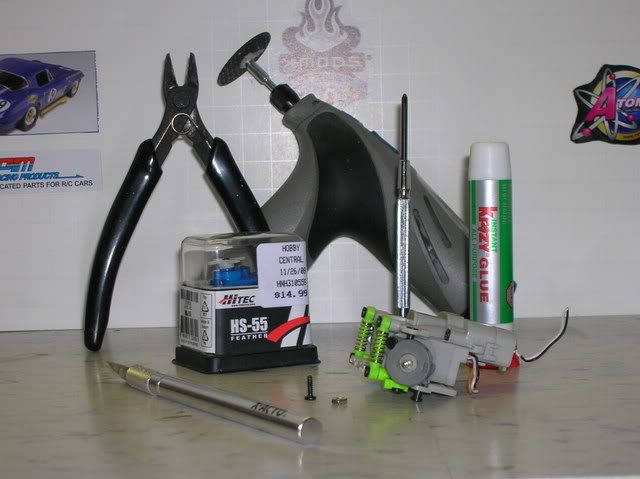 OOPS forgot these 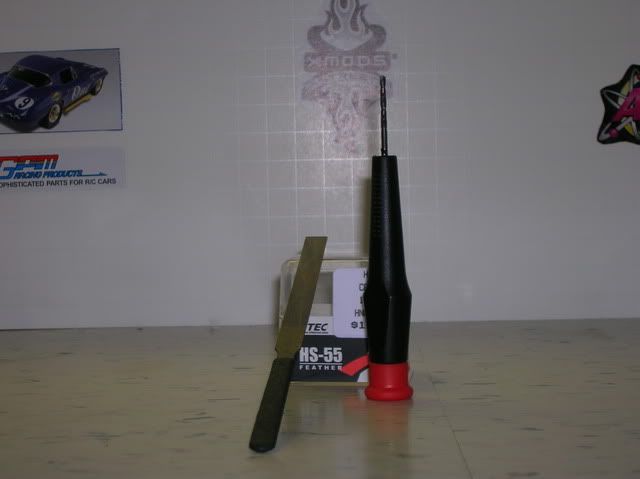 STEP 1 - No photo for this. **MAKE SURE TO REMEMBER WHERE ALL WIRES GO BEFORE CUTTING THEM OFF. I suggest taking photos of everything when you start and as you go, when memorization is needed. STEP 2 - Remove the cover to the servo motor by pull open the tabs. 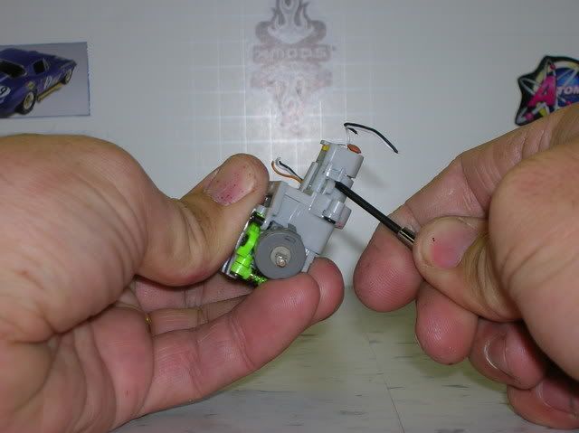 STEP 3 - Pull out the servo motor. 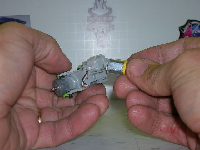 STEP 4 - Take your front end and remove everything. Shocks, knuckles, A arms. 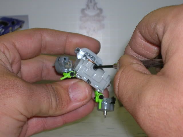 STEP 5 - pop out the POT and the servo board and pull the wires out. 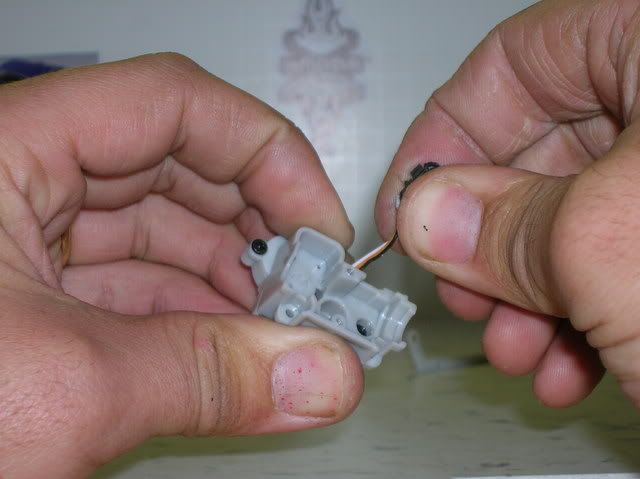 STEP 6 - Unscrew the 3 screws to seperate the front end casing. 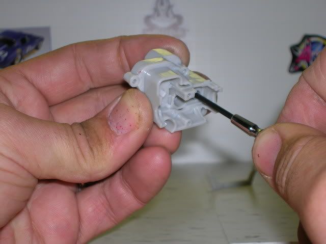 STEP 7 - Now we start cutting. Take the back side of the front end case and cut off the portion in red. This should leave it flat on this side. 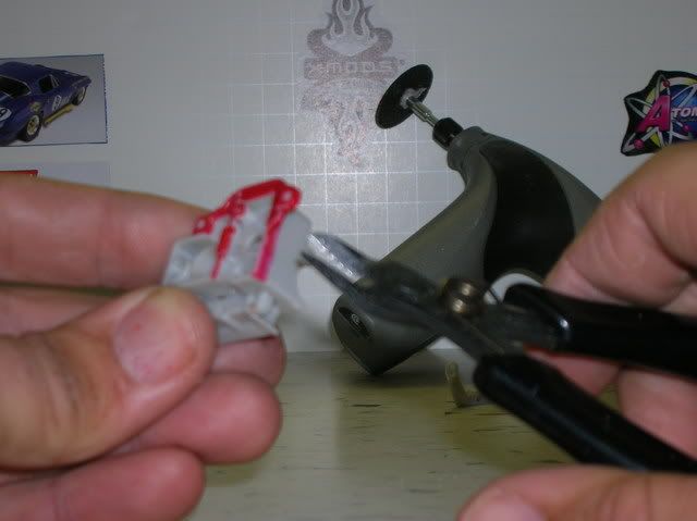 Should look like this. 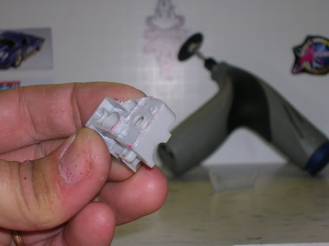 Be sure to cut off the side of the circle opening where the drive shaft goes. This will let your servo have a clean swing left to right. 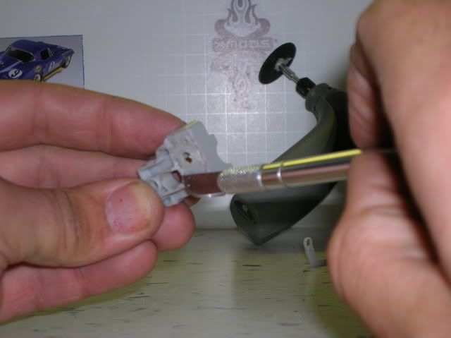 Using your file, sand paper, exacto knife or dremel and make it squeaky clean and purrrrty. 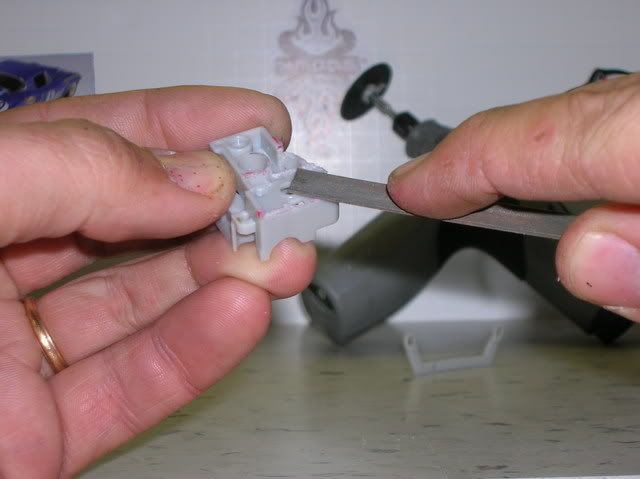 STEP 8 - Now take the swing arm and cut out the red portion you see in the photo. A dremel works best, but you can use an exacto knife. Careful with snipes because they can crack it. 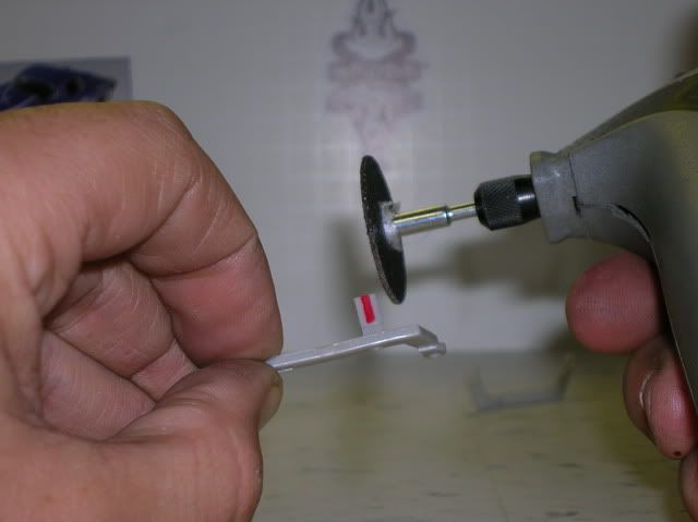 Should look like this. 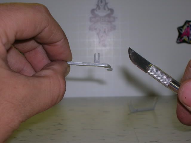 STEP 9 - Take the long arm and firgure out the length you need. (This will be different for everyone and depends on what chassis you use ie: stock, stilletto, or a custom chassis. Once you know what length you need take the small drill bit from yout Xmod tool kit. Carfully drill a hole and attach it to the servo. 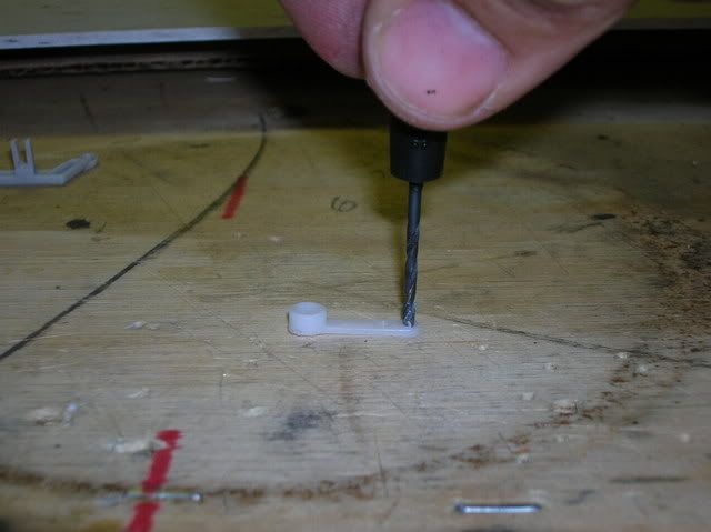 Should look like this. 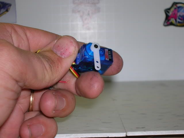 STEP 10 - Take an Xmod screw and a RS 2/56 nut and attach them to the arm like this. 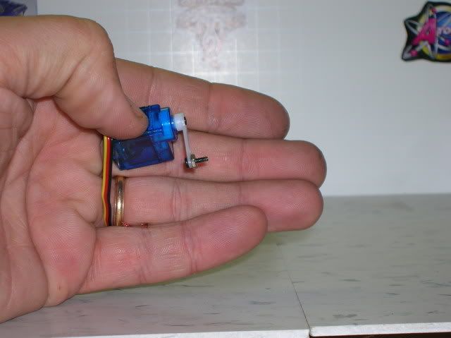 STEP 11 - The screw will go in the swing arm like this, so test fit it and make sure it is loose. If its not loose dremel out the swing arm a little more. (There should be play and not tight) 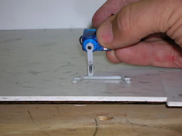 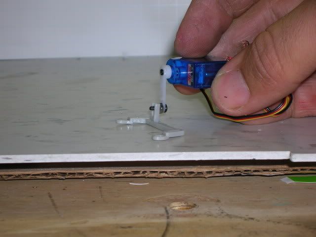 Should be loose so that it will work smooth, like this. 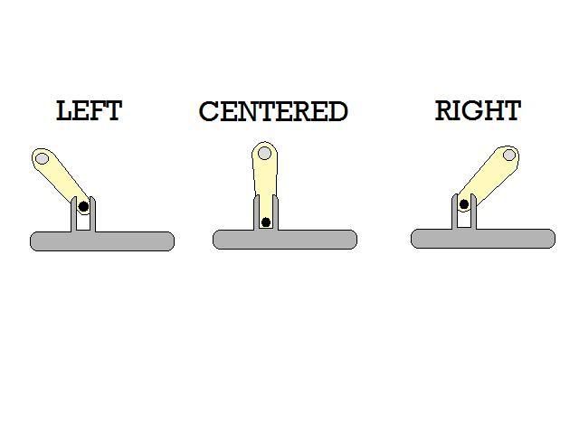 STEP 12 - Go ahead now and re-assemble your front end completly ( dont put the back side of the casing back on, you can throw that in your spare parts box. 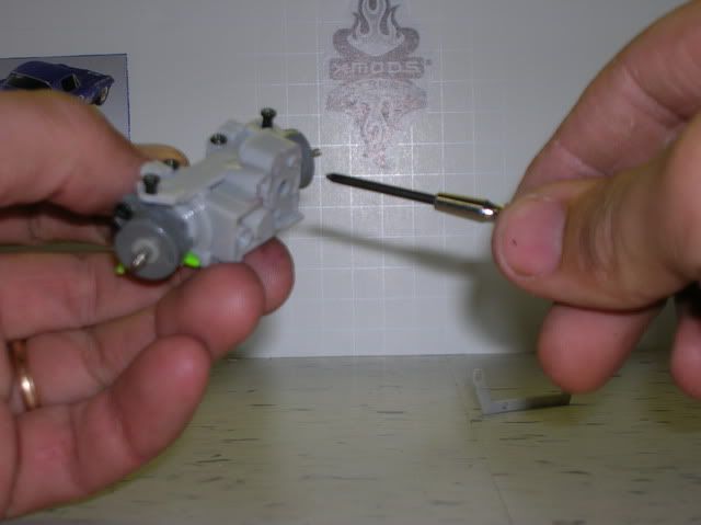 STEP 13 - Okay, now thats done on to the electronics. (Remember to note where all wires go before cutting them off) Take out the 4 screws in the Micro servo (HS-55 for tutorial) 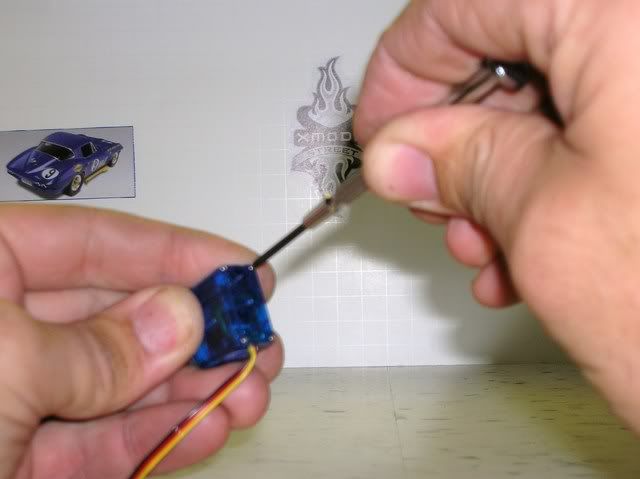 Gently pull out the board and stretch out the wires inside. You should have this. 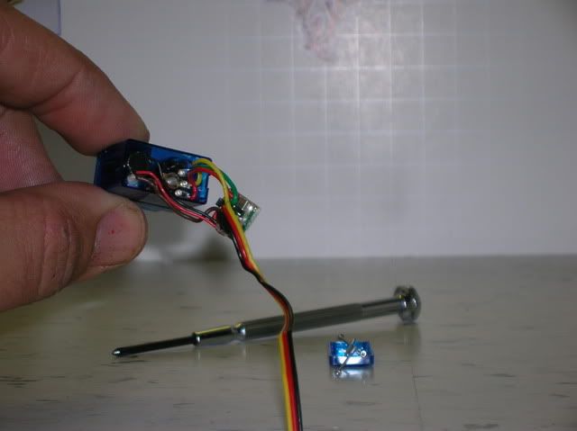 STEP 14 - Cut the 3 POT wires from the board, just like this. 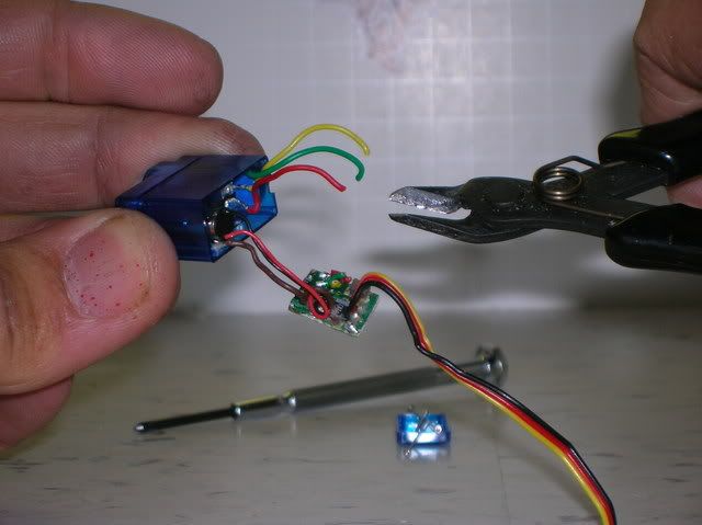 STEP 15 - Cut the Black and Red motor wires from the board, just like this. 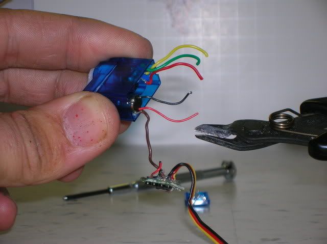 STEP 16 - Cut the brown wire off at the motor (you should desolder it, but snip it as close to the motor as possible if you cut it). Like this. 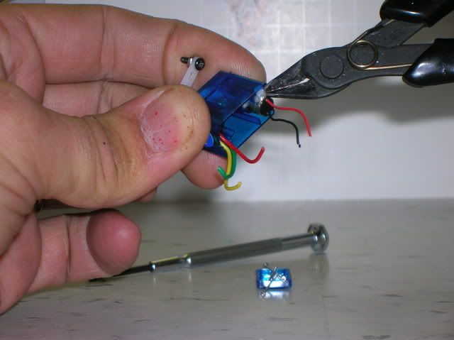 STEP 17a - Okay, now connect the servo to the board like this. You can decide to use all new wires or splice, just becareful and don't be sloppy. 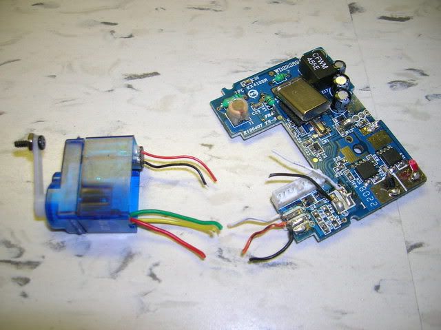 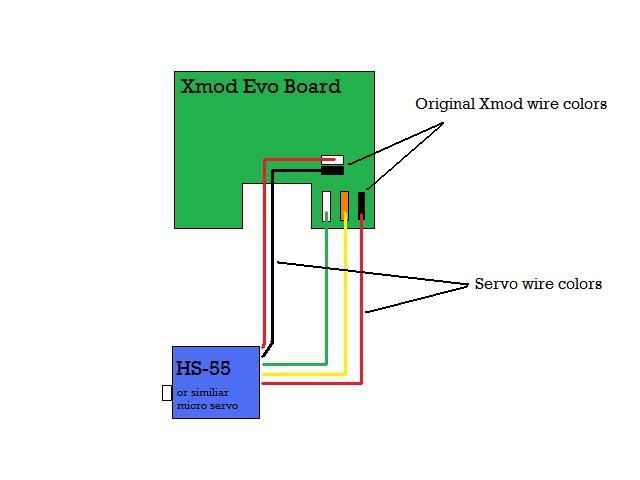 STEP 17b - Make it clean and cool. Drill 2 holes in your servo cover. Slide the cover over the wires before you solder them to the board. Just like this. 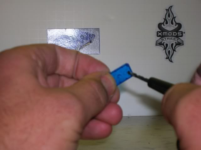 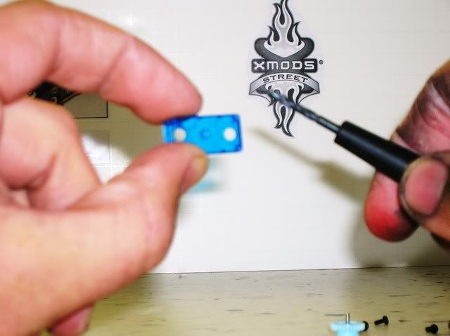 Mmmmmm, that's purrrty. 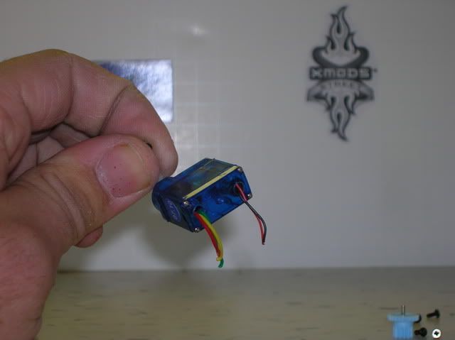 STEP 18 - Well that's it. Use some double sided tape or superglue and attach it to your chassis. Enjoy and here's a video, my batteries were low on the car but you get the idea.  ************************************************** ******* What Tutorial would everyone like to see next. PM me and keep the clutter out of the thread so that people can post their questions easier. THANKS.
__________________
 XXX FREE modding Service: http://www.xmodsource.com/forum/showthread.php?t=17800 PM me for a quote or any questions. HAPPY MODDING 100% Positive Itrader feedback http://www.xmodsource.com/forum/itrader.php?u=6901 Last edited by TripleXmodder(akaXXX); 01-05-2009 at 12:08 AM.. |
| Currently Active Users Viewing This Thread: 1 (0 members and 1 guests) | |
|
|